SMART PARKING: KEYDRIVER FOR SMART CITIES

A smart city is an urban area in which, thanks to the use of digital technologies and more generally of technological innovation, it is possible to optimize and improve the infrastructures and services to citizens, making them more efficient.

According to a classification made by the University of Vienna, there are 6 factors that distinguish a smart city, that is:

  • Smart economy
  • Smart living
  • Smart environment
  • Smart mobility
  • Smart people
  • Smart governance

KEYWORD: CONNECTIVITY

The combination of smart city and connectivity will lead to a new frontier of mobility in which data-driven technologies will make the difference.

Technological innovation and, in particular, the Internet of Things (IoT) has opened the doors to countless possibilities; Sensor networks and Long Range technologies (LoRaWAN) are the basis of the smart revolution in every area of city management (think of smart lighting systems, smart metering, etc.).

But intelligence also means guaranteeing the inhabitants a more sustainable city and infrastructures capable of improving the quality of their life, which means greater attention to the environment, but also to mobility.

According to the EPA (European Parking Association), 30% of urban pollution depends on traffic due to the search for parking. Not only CO2 emissions are increasing but also the stress of motorists who are estimated to spend between 2.5 and 10 days a year looking for a parking space, with an average annual waste of diesel fuel of about € 310.

SMART PARKING is the solution

To cope with the situation, it is possible to use one of the many smart parking systems available on the market, some of which are also very complex and able to integrate with parking surveillance and payment systems, with a consequent financial commitment on the part of the buyer.

But the benefits are significant and can already be obtained with a low cost but technologically advanced system such as our Open Parking.

Born in collaboration with some municipal bodies, the project involves the installation on the stalls of special magnetic technology sensors, able to read the presence or absence of a vehicle on the stall and send the communication to a central platform using the low range network ( LoRa).

The information is provided to users in charge of control, but also to surveillance and to citizens who, through an app, will be able to easily identify free stalls and be guided along the route. They will also be able to report any dangerous conditions on the stall, infringements by other users or malfunction of the app.

The advantages deriving from the installation of Open Parking are even more relevant if related to the economic investment required: low consumption, low maintenance required, and long battery life mean that in addition to being smart, Open Parking is also a solution low cost.

Traffic Monitoring: 3 detection tools

A traffic monitoring system can be considered as an information chain consisting of the following parts:

  • Sensor: device that produces a signal describing the characteristics of the phenomenon to be detected
  • Detector: encodes the information detected by the sensor
  • Trasmission System: transfers the coded information to the central unit
  • Treatment System: processes the data according to the purpose for which they were collected.

Detection methods are essentially two:

  • Manual: detection is performed by a human operator
  • Automatic: detection takes place through ad hoc systems

For long-term operations, the automatic mode is certainly more suitable as it allows data to be collected reliably and accurately.

An automatic monitoring system usually consists of four basic components:

A detector, an interpreter, a recorder and a computer.

There are various detection technologies to choose from depending on the purpose being pursued.

Among the most common: inductive loops, triboelectric cables and pneumatic tubes.

Inductive Loops

An inductive loop is nothing more than a winding of electric wire, normally consisting of one or two turns arranged in a square or rectangular shape; the current that passes inside the wire generates a magnetic field that undergoes a variation as the metal structure of the vehicle passes; this variation produces an electrical signal that allows the detection of the passage (as well as of the characteristics) of the vehicle.

A monitoring system based on inductive loops generally consists of one or two loops placed on the sides of the carriageway and connected to a detector device. The loops can be installed above the pavement or embedded in the road surface depending on whether the detection system is temporary or permanent.

To date this appears to be the most widely used method. The reasons can be traced back to low costs (mostly related to installation), the accuracy of the measurements that are not affected by atmospheric phenomena and the long life of the instrument.

Pneumatic Tubes

ensor consisting of a pneumatic tube positioned on the carriageway and connected to a counter device placed at the edge of the road. When the wheels of a vehicle crush the pneumatic tube, a pressure wave is generated inside it which generates an impulse in the meter.

Ease of installation and low cost are the main advantages of the sensor which, however, also has some disadvantages, including:

  • counting inaccuracy in the case of high flows
  • the impossibility of obtaining the transit data of multiaxial vehicles (in fact a truck with six axles is detected as three u.v.e.)
  • danger of detachment of the pipe from the road pavement
  • the inability to count on multiple lanes
  • the risk of mechanical breakage of the tube especially by heavy vehicles

Triboelectric Cables

Similar to that with pneumatic tubes, but it is based on the triboelectric effect, that is the electrification by rubbing of a dielectric material. In practice, when the wheels of a vehicle pass over the cable, the steel wires of the outer ring of the cable rub the surface of the dielectric material, electrifying it, and thus causing an accumulation of electric charge; this involves sending an electrical signal and therefore recording the passage of the vehicle axis.
Therefore, similar to pneumatic tubes, triboelectric cables count the vehicles in transit starting from the detection of the axles of the vehicles themselves. However, compared to pneumatic tubes, triboelectric sensors are to be preferred because they are more robust and resistant, less visible and in any case not much more expensive.

Do you know what a Supersonic Bang is?

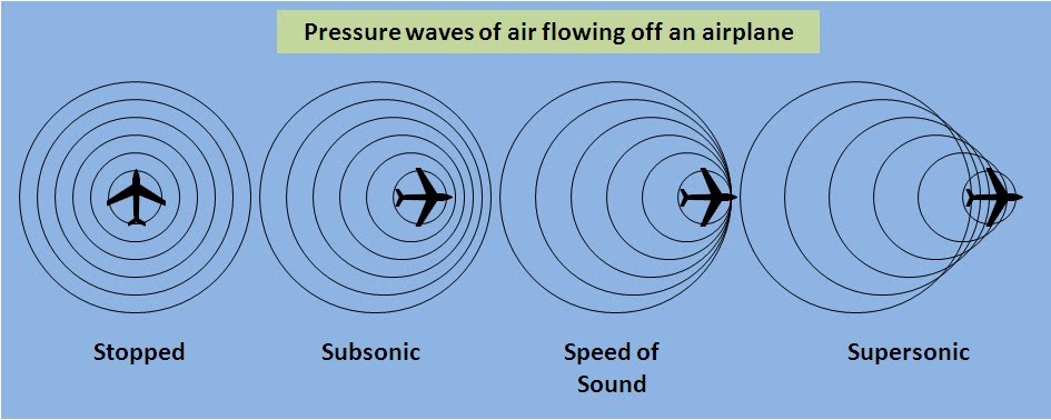
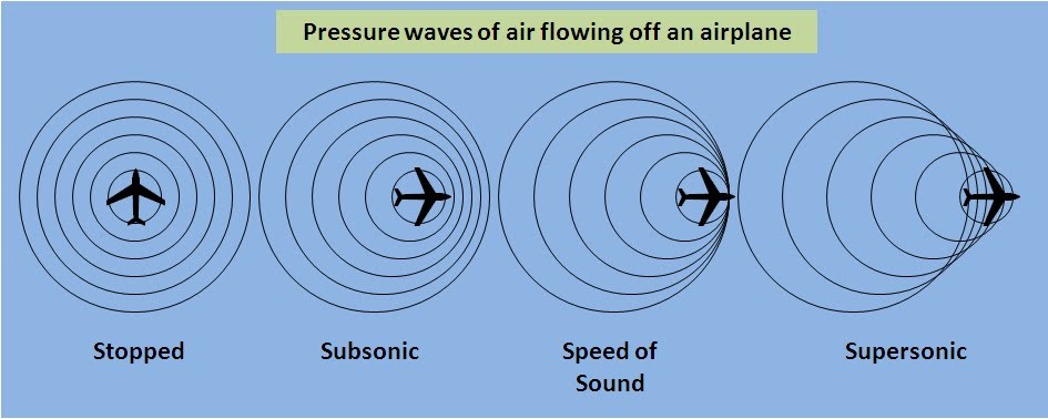
Any object that produces noise, generates sound waves (simple pressure variations) that spread in the air in a uniform and concentric way with respect to the source; if the object moves, as in the case of an airplane, these waves will generate a conical shape, that is they will be closer to each other in the direction in which the object proceeds and more spaced behind it.

In this picture, pressure waves of air flowing off an airplane

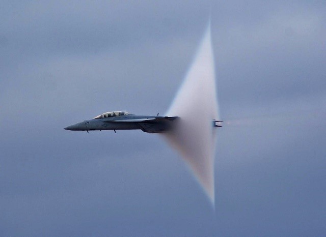
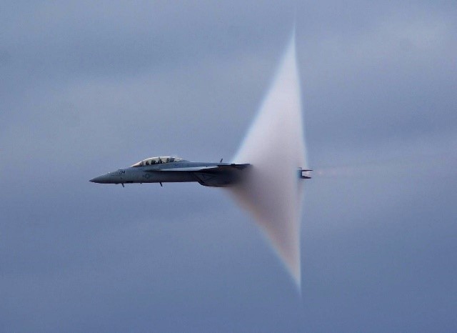
The faster a plane goes, the more the waves are compressed with one another, until, reaching the speed of sound, they add up to each other: at which point the plane will break the sound barrier, producing a strong noise (whose intensity will be the sum of the sound waves produced) that will continue until the plane continues to proceed at supersonic speed (but it will continue to be audible only by those who are “inside” the MACH CONE and that follows the moving object).

In this picture, the sound barrier is broken by an Eurofighter

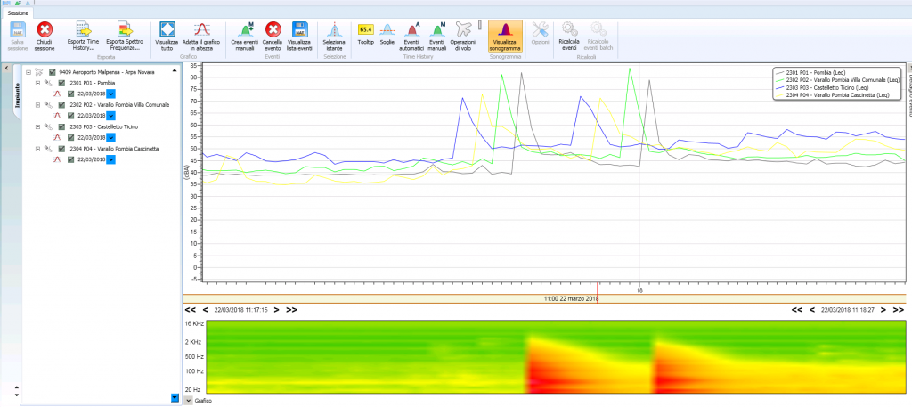
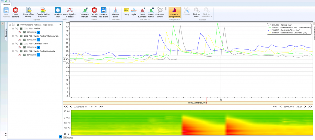
Last year our noise monitoring systems recorded the sonic bang produced by two Eurofighters of the Italian Air Force that took off to intercept an Air France Boeing 777 aircraft that had lost radio contact with the Italian control bodies; the event had great media coverage and caused concern among the people of Northern Italy, frightened by the loud noise.

These are the acoustic profiles of the monitoring stations: it is easily recognizable the moment in which the two Eurofighters have broken the wall of sound, creating the boom. The acoustic spectrum infact shows at that time two peaks very similar to the image of the broken sound barrier.

In such a situation, our systems recognize the anomaly of the recorded event and, if properly configured, send an alarm to the user.

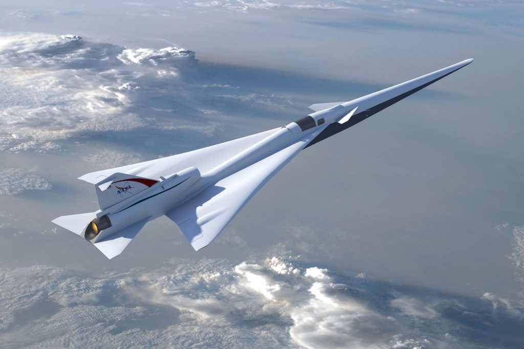
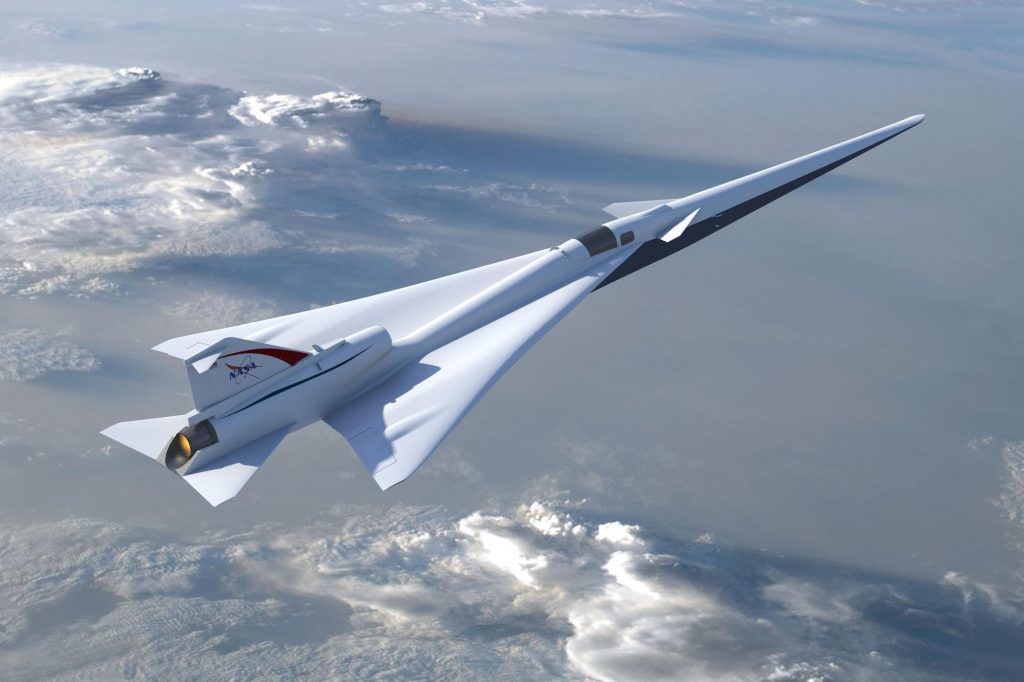
The cases of sonic boom do not occur frequently (in 2017 they have been 64 worldwide) and in the future they may even decrease; infact, the first flight of the Lockheed Martin X-59 QueSST (where QueSST stands for Quiet Supersonic Transport) is expected in 2021. It is the experimental low-sonic boom developed by NASA (known as X- plane) and built by Lockheed Martin; It will be about thirty meters long, a little less than a Boeing 737, and can reach Mach 1.4 speed (speed of sound Mach=1), around 1,800 km / h. If it enters service, it will allow halving flight times on medium-haul routes.

in this picture the X-plane. The special form of wings and fuselage allows it to break the sound wall almost silently

But how can a supersonic plane not produce the bang when it overcomes the wall of sound?

This is due to the particular shape of wings and fuselage that allows it to cleave the air better and that give a particular conformation to the sound waves produced by the device; It should create a 75 Perceived Level decibel (PLdB) thump on ground, as loud as closing a car door, compared with 105-110 PLdB for the Concorde (that is one of only two supersonic transports to have been operated commercially; the other is the Soviet-built Tupolev Tu-144).

Mai sentito parlare di “Supersonic Bang”?

Qualsiasi oggetto che genera rumore, genera onde sonore (semplici variazioni di pressione) che si diffondono nell’aria in modo uniforme e concentrico rispetto alla sorgente; se l’oggetto si muove, come nel caso di un aeroplano, queste onde genereranno una forma conica, cioè tenderanno ad essere più vicine tra loro nella direzione in cui procede l’oggetto e più distanziate dietro di esso.

In questa immagine, le onde di pressione dell’aria che fluiscono da un aeroplano

Qualsiasi oggetto che genera rumore, genera onde sonore (semplici variazioni di pressione) che si diffondono nell’aria in modo uniforme e concentrico rispetto alla sorgente; se l’oggetto si muove, come nel caso di un aeroplano, queste onde genereranno una forma conica, cioè tenderanno ad essere più vicine tra loro nella direzione in cui procede l’oggetto e più distanziate dietro di esso.
Maggiore la velocità dell’oggetto, minore la distanza delle onde che si comprimono fino a sommarsi nel momento in cui si raggiunge la velocità del suono: a questo punto l’aereo rompe la barriera del suono. Il risultato è un forte rumore (la cui intensità essere la somma delle onde sonore prodotte) che si protrarrà fino a quando l’aereo continuerà a procedere a velocità supersonica (ma continuerà ad essere udibile solo da chi è “dentro” il MACH CONE e che segue l’oggetto in movimento).

In questa foto, la barriera del suono è rotta da un Eurofighter

Tempo fa, i nostri sistemi di monitoraggio del rumore hanno registrato il rumore sonico prodotto da due Eurofighter dell’Aeronautica Militare decollati per intercettare un Boeing 777 dell’Air France che aveva perso il contatto radio con gli organi di controllo italiani; l’evento ha avuto grande risonanza mediatica e ha destato preoccupazione tra la popolazione del Nord Italia, spaventata dal forte rumore.

Dai profili acustici delle stazioni di monitoraggio (nella figura sotto) è facilmente riconoscibile il momento in cui i due Eurofighter hanno infranto il muro del suono, creando il boom. Lo spettro acustico mostra infatti in quel momento due picchi molto simili all’immagine della barriera del suono rotta.

In tale situazione i nostri sistemi riconoscono l’anomalia dell’evento registrato e, se opportunamente configurati, inviano un allarme all’utente.

I casi di sonic boom non si verificano frequentemente (nel 2017 sono stati 64 in tutto il mondo) e in futuro potrebbero addirittura diminuire; infatti, il primo volo del Lockheed Martin X-59 QueSST (dove QueSST sta per Quiet Supersonic Transport) è previsto nel 2021.
È il boom sperimentale low-sonic sviluppato dalla NASA (noto come X-plane) e costruito da Lockheed Martin; Sarà lungo una trentina di metri, poco meno di un Boeing 737, e potrà raggiungere la velocità di Mach 1.4 (velocità del suono Mach=1), circa 1.800 km/h. Se entrerà in servizio, consentirà di dimezzare i tempi di volo sulle rotte di medio raggio.

in questa immagine l’X-plane. La speciale forma delle ali e della fusoliera gli consente di rompere il muro del suono quasi silenziosamente

Ma come può un aereo supersonico non produrre il botto quando supera il muro del suono? Ciò è dovuto alla particolare forma delle ali e della fusoliera che gli permette di fendere meglio l’aria e che danno una conformazione particolare alle onde sonore prodotte dal dispositivo; Dovrebbe creare un tonfo a terra di 75 decibel di livello percepito (PLdB), forte come la chiusura di una portiera di un’auto, rispetto ai 105-110 PLdB del Concorde (che è uno dei due soli trasporti supersonici ad essere stati utilizzati commercialmente; l’altro è il Tupolev Tu-144 di costruzione sovietica).

SIDs & STARs: Let’s discover the Standard Instruments

Standard instrument departures (SIDs) and standard instrument arrivals (STARs) are charted instrument procedure designs depicting the lateral profile that pilots must follow for landing or departing at suitably equipped aerodromes. Various level and speed restrictions apply along the route.

There is a standardized system of communication for SID and STAR procedures to ensure efficient and concise communication that would otherwise require long and complex radio transmissions between the pilot and air traffic control.

SID and STAR designs and standardized transmissions are an effective way of communicating a large amount of complex information for safe and efficient departures and arrivals and are in place worldwide through the International Civil Aviation Organization (ICAO).

There are 3 types of SID:

  1. Straight departure: procedure that does not require a turn greater than 15 ° with respect to the extension of the centerline of the runway.
  2. Turning departure: it is a type of procedure which requires a turn greater than 15 ° with respect to the extension of the centerline of the runway, the first turn must be performed upon reaching the TP (Turning Point) which guarantees minimum separation from the highest obstacle below it 120 m. This separation may vary according to the morphology of the terrain and the average wind recorded in the airport area.
  3. Omnidirectional departure: this is a type of procedure in which there is usually no radio assistance available to pilots to perform a normal SID. Pilots will be able to tack in any direction upon reaching a point published on the procedure map.

The carrying out of a SID is the responsibility of the pilot in command.

SARA software “Tracks” function

Some SIDs are developed solely to meet noise abatement requirements.
These types of restrictions require higher altitude starts, higher elevation gains, slower speeds and veers to avoid specific areas.

Airports monitor the correct application of the procedures for implementing the noise abatement rules.

Among the feasible solutions, the choice of a noise data monitoring and management system that also allows the analysis of radar tracks, such as SARA. In fact, our platform allows the airport to verify compliance with the SIDs and to apply penalties where necessary, so as to encourage compliance with noise abatement procedures.

SIDs & STARs: let’s discover the standard instruments!

Standard instrument departures (SIDs) and standard instrument arrivals (STARs) are charted instrument procedure designs depicting the lateral profile that pilots must follow for landing or departing at suitably equipped aerodromes. Various level and speed restrictions apply along the route.

There is a standardized system of communication for SID and STAR procedures to ensure efficient and concise communication that would otherwise require long and complex radio transmissions between the pilot and air traffic control.

SID and STAR designs and standardized transmissions are an effective way of communicating a large amount of complex information for safe and efficient departures and arrivals and are in place worldwide through the International Civil Aviation Organization (ICAO).

There are 3 types of SID:

  1. Straight departure: procedure that does not require a turn greater than 15 ° with respect to the extension of the centerline of the runway.
  2. Turning departure: it is a type of procedure which requires a turn greater than 15 ° with respect to the extension of the centerline of the runway, the first turn must be performed upon reaching the TP (Turning Point) which guarantees minimum separation from the highest obstacle below it 120 m. This separation may vary according to the morphology of the terrain and the average wind recorded in the airport area.
  3. Omnidirectional departure: this is a type of procedure in which there is usually no radio assistance available to pilots to perform a normal SID. Pilots will be able to tack in any direction upon reaching a point published on the procedure map.

The carrying out of a SID is the responsibility of the pilot in command.

SARA software “Tracks” function

Some SIDs are developed solely to meet noise abatement requirements.
These types of restrictions require higher altitude starts, higher elevation gains, slower speeds and veers to avoid specific areas.

Airports monitor the correct application of the procedures for implementing the noise abatement rules.

Among the feasible solutions, the choice of a noise data monitoring and management system that also allows the analysis of radar tracks, such as SARA. In fact, our platform allows the airport to verify compliance with the SIDs and to apply penalties where necessary, so as to encourage compliance with noise abatement procedures.